

How To Cut And Draw On Silhouette Cameo
Explorations with the
Silhouette Cameo Cutter
by Cathy Saxton
Posted December 3, 2011
Concluding Updated September 10, 2012
I got a Silhouette Cameo plotting cutter and have been using it for a variety of purposes.
My experiments and tips are beneath, merely beginning, a story from when I received the cutter. It came in a gigantic box. I opened that to find a bunch of packing paper and another brown paper-thin box, most one-half the size of the kickoff ane. (It looks like that was used to ship from the distributor to the retailer.) I opened the second box and plant a third box. At that signal, my husband, Tom, speculated that I'd keep opening successively smaller boxes until I got to the final i with an X-Acto knife and a ruler.
And at present the usual disclaimer: I make no guarantees that my techniques will work for you, or that they won't damage your machine, blade, or mat. That said, I hope you observe some useful tidbits on this page!
The side by side several sections are some general observations and tips. Afterwards that are three sections with steps for a specific project:
- How to make an integrated card represent cards with the fold on top.
- A technique for cutting out a stamped image.
- Cut a stencil from 3 mil mylar. I use this to utilize solder paste for soldering surface-mount components on a PCB.
Experiments with Rotations when using Registration Marks
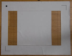
I was interested to see whether the cutter assumed a perfectly aligned paper, since it's challenging to achieve this. I created a unproblematic cartoon with registration marks and cut-out squares in the corners, then printed it (but the registration marks print, of course).
My first several attempts at mounting the folio at a noticeable bending failed. I was doing an extreme angle (~1/2" drib over the 11" length of the page) and so information technology would be easy to see whether the squares got cut in the right place (and angle). The outset indication that information technology wasn't happy was that I had to employ detect registration marks manually. That worked in 1 of two cases, but the squares weren't cut correctly; information technology had correctly accounted for rotation vertically, simply non horizontally. For the second test (rotated the other direction), the Cameo failed to detect the registration marks. Notation that my extreme rotation cases were outside what could reasonably be expected when mounting a page on the mat, and then I don't error the machine for not coping with them.
Next, I tried a less farthermost bending, more than like how a page might exist mounted but slightly off, but however plenty of a noticeable tilt that I'd be able to measure out and make up one's mind whether it adjusted for the rotation. That worked beautifully!
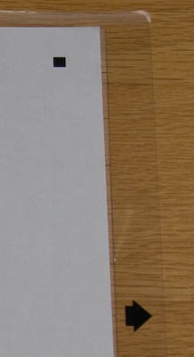
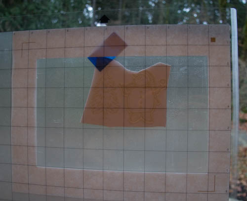
The picture on the right shows the page mounted slightly askew on the cutting mat. As you can come across from the pointer, the top of the cutting mat (first function into the machine) is on the right side in this photo. In this orientation, the xi" side of the paper is vertical and at that place are squares cutting near the right edge, close to the top and bottom.
The pictures below are close-ups showing the distance from the cut to the edges of the paper, sticky area, and mat. The first photograph is the top foursquare, the 2nd photo is the bottom square. Notice that the distance from cutting to edge of paper is the same in both, and y'all can see how the paper was crooked, closer to the border of the sticky area in the lower photo.
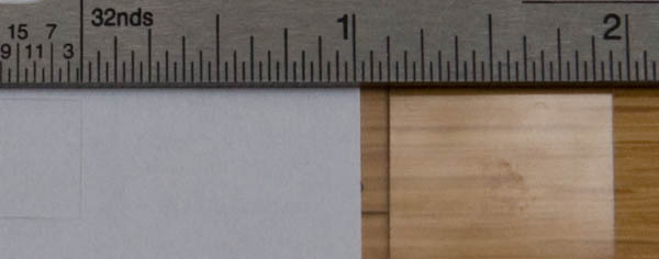
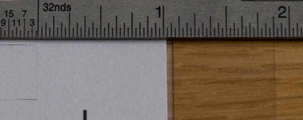
Measurements forth the top border of the paper were similar, showing that the cutter did correctly account for the rotation of the folio. Yay!
Decision: The Cameo cuts correctly (rotating the blueprint) even if the page with registration marks is mounted slightly kleptomaniacal on the cut mat.
Compensating for an Overly-Aggressive Sticky Mat
I institute that peeling off a large piece of cardstock was challenging and tended to outcome in pretty major warping and sometimes wrinkling. In my case, I was making a few small cuts to the menu, and wanted to use the card (not the cutouts), so information technology was a problem when it got damaged during removal from the mat.
My solution was to place a sparse piece of paper under most of the eye area of the cardstock, in an area that wasn't getting cut. I found that I needed to modify my bract setting to 4 instead of the default 3 that had been working fine to cut my (Stampin' Up!) cardstock. This worked wonderfully; the cardstock was nonetheless held in place for cutting, simply was a lot easier to remove.
Thank you to Chris Savery for sharing another smashing technique that I've been using recently: Place the mat at the edge of a table, with the cut paper on top. Gradually slide the mat off the table, pulling it down and guiding the newspaper off the mat, keeping the paper parallel with the tabular array. This works well and results in very little curlicue in the paper.
Cutting at a Precise Location
Later on a few trials, information technology became apparent that I would be unable to go cuts in a precise location on a card by just mounting the cardstock to the cutting mat and inserting it into the cutter (even when placing very precisely on the mat and inserting at a consistent left-to-right location). It tended to vary by upwardly to about an eighth of an inch.
The skilful news is that the "registration mark" feature provided a nice way to ensure consistent cut locations.
The adjacent ii sections — Integrated Carte Stand and Cutting Out a Stamped Paradigm — show examples.
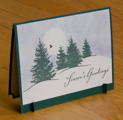
Integrated Card Stand
Cards with the fold on top (instead of left) are temperamental to display; they tend to unfold, slowly creeping toward becoming flat. There are nice options for a separate stand that tin can exist used to hold the card and keep it from sliding apart.
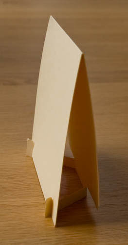
I decided I wanted to make a card with an integrated stand, so I did some experimenting and designed a arrangement that created "legs" from the dorsum cardstock.
The menu is a standard one-half sheet (8 1/two" x 5 ane/2") folded to four 1/4" alpine x 5 1/ii" wide. The legs are one iii/4" long and 1/4" loftier, with the feet extending up to i/2". Slits in the front are ane/four" long, three/4" in from the edges.
I made prototypes using my trusty X-Acto knife, just used this project equally my alibi to get a cut motorcar. :-) It has turned out to be useful for other projects, as well.
Cut with the Silhouette Cameo
The basic strategy is to create a "template" canvas with registration marks and a cutout to provide for precise placement for the card, and so utilise a second file to brand the cuts.
Preparing the Template
- Open the Registration+viii.5x5.5cutout.studio file.
- File/Print (or utilize the Send to Printer toolbar icon), use a sparse sheet of paper (not cardstock).
- Mount the printed page to the cut mat (in upper left corner, in mural orientation).
- File/Cutting Settings (or click the icon for the Silhouette Cut Settings window).
- In the Silhouette Cut Settings window: Ostend that "Print Paper (light)" is selected.
- Adjust your bract pinnacle to 1 (this is the physical aligning, not a program setting).
- File/Send to Silhouette (or click the toolbar icon or button at the bottom of Cut Settings).
- In the Print Image window: click the link to skip printing.
- In the Transport to Silhouette window: follow instructions to load the cutting mat, click Continue.
- In the Cut Image window:
- Click "Observe Automatically" (for registration mark detection).
- (Expect for detection to complete.)
- (Verify the current settings, adjust via Cutting Settings if necessary.)
- Click "Cut page."
- Unload the cutting mat.
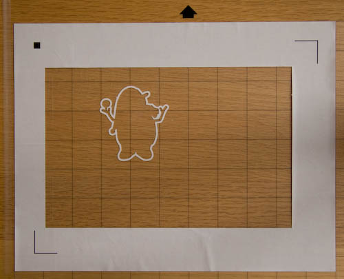
- Peel off the paper in the left-virtually and right-about strips of the 8.five x five.5 area (left photograph below). These are the sections in which cuts will be fabricated, and the areas of the carte du jour that will exist cut need to be held fast past the mat. Leaving the chunk of newspaper in the centre makes information technology a lot easier to remove the cardstock, especially without damaging or curling information technology.
Cutting the Card
- Open up the Registration+StandCuts.studio file.
- File/Cut Settings (or click the icon for the Silhouette Cut Settings window).
- In the Silhouette Cut Settings window: Ostend that "Cardstock (heavy)" is selected.
- Adjust your blade height to 4 (this is the physical adjustment, non a program setting). The Cutting Settings window says 3, just we need the actress height because of the paper behind the centre of our cardstock.
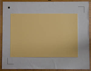
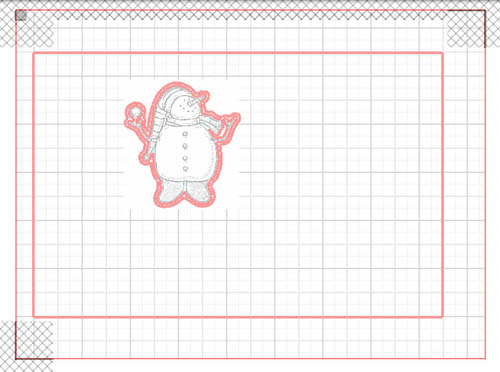
- Mount the cardstock in the cutout area of the template (right photo above).
- File/Ship to Silhouette (or click the toolbar icon or push at the bottom of Cutting Settings).
- In the Print Image window: click the link to skip press.
- In the Transport to Silhouette window: follow instructions to load the cut mat, click Go on.
- In the Cut Image window:
- Click "Detect Automatically" (for registration mark detection).
- (Await for detection to consummate.)
- (Verify the current settings, adjust via Cut Settings if necessary.)
- Click "Cutting page."
- Unload the cut mat.
- Remove the carte du jour from the mat.
- You can mount a new card, load the mat, and repeat the steps in the Cut Image window (detect, wait, cut).
Finishing the Card
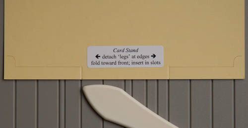
Score the legs where they should curve toward the front. I put a sticker on the dorsum of the card with instructions.
As you tin see in the photo above, I decided non to extend the "human foot" cut all the way to the edge; that way the legs aren't loose and flopping effectually.
For the front and within, I cut white cardstock five 1/4" ten 3 3/4". On the within one, I punched the ii lower corners with the ticket corner punch; this matches the arc from the cut on the anxiety.
Cut Out a Stamped Image
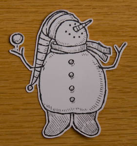
For computer clip-fine art, press and cutting out an image is easy — just add together registration marks to the artwork, print, and the cutter knows exactly where to cut.
With a stamped paradigm, however, nosotros need to do a fiddling more than work to define the relationship betwixt the prototype and registration marks. Nosotros do this by using a template that shows the location of the cut relative to the registration marks. The template will guide the placement of the stamped cardstock onto the cutting mat.
We'll create 2 files: one for cutting the outline, and another to create the template.
Setting upwardly the Files
We'll commencement by creating the OUTLINE file, then volition add to it to create the TEMPLATE file.
- Stamp your image on cardstock.
- Scan the epitome. Salvage as a JPG file.
- In Silhouette Studio, File/Open, select the JPG.
- In the Folio window, select Letter (8.5x11).
- In the Registration Marks window, check Show Reg Marks.
- In the Grid window, check Show Grid. Y'all can check/uncheck the Snap to Grid box every bit yous're working, based on what beliefs you lot want.
- Motion the paradigm to desired location.
- Zoom in so the image nearly fills the window. Yous'll want to take a trivial bit of the filigree showing around the edges.
- File/Salve, choose a name. This volition become the OUTLINE file.
Creating the OUTLINE File
- In the Trace window:
- Click the Select Trace Area button.
- Click and drag to select the unabridged expanse containing your prototype.
- Click Trace Outer Edge (for Trace Method).
- Click on the arrow tool (Select) at the peak of the left vertical toolbar.
- In the Cut Fashion window:
- Click precisely on the red line. This is tricky. If you lot succeed, the Cut Style list will take "Cut" selected. Otherwise it will evidence No Cut (or won't have any option). If y'all don't get the line selected, click outside the prototype to remove the pick and try over again.
- In one case the red line is selected, modify the selection to No Cutting. We don't actually want to cut this close; in the steps below, nosotros'll aggrandize this outline and cut on that line.
- In the Line Color window, choose something unique. In my example, I used yellowish. This will aid yous distinguish when it's selected (by looking at the highlighted color in the Line Color window).
- In the Offset window:
- Click Offset.
- Set up the distance to 0.03".
- (utilize Rounded, not Corner, in the listing at the lesser.)
- Click the Apply button.
- In the Line Colour window, choose another color, e.thou. bluish.
- In the Cut Style window, select "Cut" in the list.
- Relieve the file. Your OUTLINE file is now complete.
Creating the TEMPLATE File
For the template, we'll cut the outline that we want to use on the card, then some other outline merely slightly larger; this will give us a narrow band to guide placement of the menu. We'll also cut a large rectangle on the template to provide a big exposed (sticky) expanse on the mat.
Note that the steps below are causeless to immediately follow the steps above. Specifically, it is assumed that the blue outline cut is selected. To verify that, open the Line Colour window and make certain that the blue block is highlighted and that a selection is shown effectually your stamped epitome. If the bluish outline cutting is not selected, y'all can select information technology by clicking precisely on it; if the blue block isn't highlighted, click on the grid area to remove the selection, so try again.
- File/Salvage Equally, give information technology a new proper name. This volition get your TEMPLATE file.
- Get back to the Offset window, click Start, gear up distance to 0.06", and click Use.
- In the Line Color window, choose some other colour, east.g. green.
- (You can verify that this new line volition be cut in the Cut Mode window.)
- Zoom out and then you can see the entire canvass of newspaper. I employ the "Fit to Window" toolbar icon (on the height horizontal toolbar).
- Select the "Describe a Rectangle" tool (on the left vertical toolbar) and describe a large rectangle slightly inset from the edge of the newspaper. This is the expanse where the mat volition be exposed for holding the stamped cardstock. (Turn on Snap to Grid for this pace if you want.)
- File/Salvage. Your TEMPLATE file is now consummate.
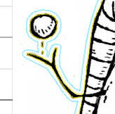
If you open up the Cut Style window, your paradigm should be like to this:
The outermost ruby-red line is related to the registration marks and won't be cut. The inner rectangle bounds the area that will be removed to expose the mat. The stamped image has a double cut line, shown in close-up in a higher place.
Preparing the Template
- File/Print (or use the Send to Printer toolbar icon), use a thin canvass of paper (not cardstock).
- Mount the printed page to the cut mat (in upper left corner, in landscape orientation).
- File/Cut Settings (or click the icon for the Silhouette Cut Settings window).
- In the Silhouette Cut Settings window: Ostend that "Print Newspaper (calorie-free)" is selected.
- Adapt your blade superlative to 1 (this is the physical adjustment, not a program setting).
- File/Ship to Silhouette (or click the toolbar icon or button at the bottom of Cut Settings).
- In the Print Image window: click the link to skip press.
- In the Send to Silhouette window: follow instructions to load the cutting mat, click Continue.
- In the Cut Epitome window:
- Click "Detect Automatically" (for registration mark detection).
- (Wait for detection to consummate.)
- (Verify the current settings, adjust via Cut Settings if necessary.)
- Click "Cut folio."
- Unload the cutting mat.
- Skin off the paper in the inner section where the prototype goes. Pare off the large clamper of newspaper inside the outer cut rectangle, leaving the thin outline band around the cutout expanse. Refer to the picture show at the beginning of the "Creating the TEMPLATE File" section for an example of how this should look.
You tin can now utilize this template over again and once more to cutting out the same paradigm multiple times. But, once you lot remove the template from the mat, you'll demand to follow the steps in this section again; y'all can't simply put the pieces back on because yous won't know the spacing between the outline and registration marks.
Mounting the Cardstock on the Mat
To align the stamped image with the template's guide, I worked from the back of the mat. It's translucent, so I was able to run into through it pretty well. The issue is being able to see from the back of cardstock (which will bear upon the mat) through to the stamped image on the front. A window works well for this. (Yes, even in overcast Seattle, there's plenty of light for this during the solar day.) Of grade, a lite table would work dandy, too, but I don't have 1 of those.
I taped the stamped cardstock to the window with the back facing me (so someone outside would be looking at the front end of the image). Then, I held up the grid, aligning it so that in that location was a consistent gap all around betwixt the stamped paradigm and the template'south outline. I pressed all over the cardstock to get information technology firmly stuck to the mat, and then removed the assembly from the window, gently pulling off the mat and tape.
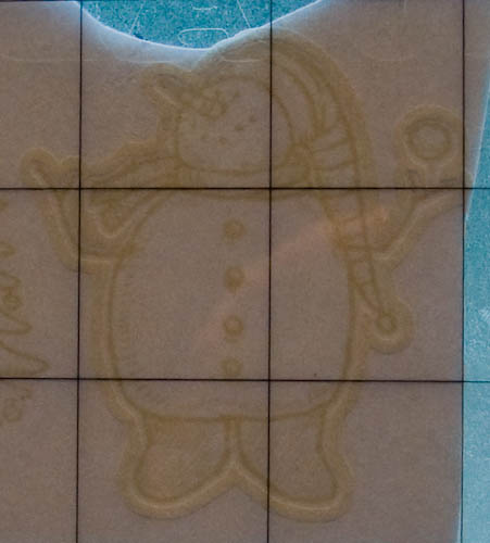
This photo shows the epitome as seen through the mat and cardstock. Note that yous can come across the template's outline shape pretty well around the anxiety. It was easier to see in person.
A couple options for alternate means to mount the cardstock image:
- You could mirror the image before creating the template and mountain the stamped prototype to the mat face up-downwardly. This would permit yous to meet it clearly through the dorsum of the mat without needing the backlight. The downside is that yous'll be putting your image directly against the sticky part of the mat. This could leave a flake of residual on your image, impairment your cardstock surface, or pull off materials y'all've used to color the paradigm.
- Instead of using your TEMPLATE file for the template, use the OUTLINE file. Print it on lightweight paper. When you mount information technology to the mat, starting time put lightweight paper downwards nether the areas that won't be cut; be certain to leave pasty mat areas around the perimeter and in the surface area where your prototype is. Cutting the outline. Gently remove the paper template from the mat. Put the template on top of your cardstock and position the image inside the template'southward cutout. Tape the two together. Place the cardstock and template assembly on the mat; remove whatever tape that is on cut lines. Note that you lot will probably only be able to apply this template a limited number of times before information technology'south worn out (warped, wrinkled, etc) from constant mountain/dismounting on the mat.
If your image is on darker cardstock, it can be challenging (or impossible) to see through it. Either of the methods above would provide a way to mount those images.
Cut Effectually the Stamped Image
- Open the OUTLINE file.
- File/Cut Settings (or click the icon for the Silhouette Cutting Settings window).
- In the Silhouette Cut Settings window: Select "Cardstock (heavy)".
- Accommodate your blade tiptop to 4 (this is the physical aligning, not a program setting). The Cutting Settings window says three, but nosotros need the extra superlative because of the paper under our cardstock.
- File/Send to Silhouette (or click the toolbar icon or push button at the bottom of Cutting Settings).
- In the Print Paradigm window: click the link to skip press.
- In the Send to Silhouette window: follow instructions to load the cutting mat, click Continue.
- In the Cut Image window:
- Click "Discover Automatically" (for registration mark detection).
- (Look for detection to complete.)
- (Verify the electric current settings, accommodate via Cutting Settings if necessary.)
- Click "Cut page."
- Unload the cutting mat and advisedly remove the cardstock and cut-out prototype.
Cutting Mylar for Solder Stencils
When soldering surface-mountain components to a PCB, I similar to utilize a stencil to use solder paste and a griddle to heat the solder.
I was hoping that my new Cameo cutter would be able to cut the 3 mil mylar that I similar to use for stencils, and it worked splendidly! I did some experiments and the Cameo made a beautiful examination stencil. The cuts are make clean and precise, equally skilful as or better than I've gotten with a lasercutter.
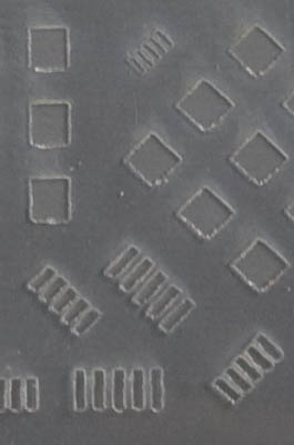
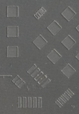
In the images below, the larger blocks are 2 mm square. The smallest cuts (meridian center) are 0.5 mm pitch spacing.
| laser-cut mylar | mylar cut with Cameo |
For iii mil (0.003" / 0.0762 mm) mylar, I was able to get a practiced cut using a blade setting of one (0.1 mm) and Silhouette Studio thickness setting of 33 (max strength). With less forcefulness, I had only a bit of problem with occasional shallow cuts. I'm using speed of 1 since I'yard making fairly small cuts.
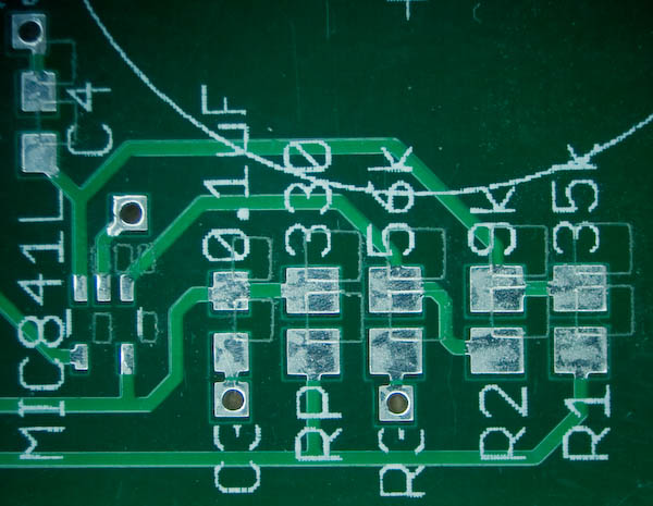
This is a photograph (through a microscope) of a board with its stencil commencement slightly correct and up. I needed to slide it a little off-centre because it's so perfect that information technology disappears when placed in the correct position! Sizes: the resistors are 0805, the capacitors are 0603, the v-pivot IC in the lower left is SC-70-five.
I was able to export DXF from Hawkeye, the PCB design software that I utilise (I've likewise got a page with tips for using Eagle), and import into Silhouette Studio, merely this step is tricky. The default DXF consign from EAGLE uses "blocks," which aren't understood by Silhouette Studio. The all-time solution I've found was suggested by Junichi Nagayama, who told me near this custom DXF exporter that creates DXF files for the top and bottom "cream" layers. In improver to creating DXF that Silhouette Studio understands, it's very convenient since it automatically uses the tCream and bCream layers; there's no demand to turn other layers off before exporting. (My original solution was to use a CAD program to catechumen the blocks to "polylines." Those steps are archived on a separate folio in case my new solution doesn't work for everyone.)
Exporting from EAGLE
Sometime setup step: Re-create foam-dxf.ulp to your Eagle ulp folder.
To export DXF files for top and bottom surface-mount pads (cream layers):
- Open up the board file.
- File/Run, cream-dxf.ulp (the DXF exporter in a higher place).
- Uncheck "Cut ii times..."
- (Leave "Cut off corners..." unchecked.)
- (Exit compress width at 0.05 mm, or alter equally y'all see fit.)
- Click Run.
This will generate filename-tcream.dxf and filename-bcream.dxf files in the binder containing your filename.brd file.
One note well-nigh DXF: Information technology appears that it does not encode an indication of units. This DXF exporter uses millimeters, which is what Silhouette Studio assumes.
Importing into Silhouette Studio and Cut
1-time setup steps: There are two settings y'all'll need to make once; both are in the Preferences dialog that you tin find on the File carte du jour (Windows) or Silhouette Studio menu (Mac):
- In the Defaults group, under "When Importing from DXF" uncheck "Scale to fit page."
- In the Advanced group, under "Parcel Size" select "500 bytes" (default is 3000). Without this change, when cutting a large/intricate design that takes a long fourth dimension (eastward.g. cutting a stencil at a slow speed), Silhouette Studio can have a problem where information technology loses the connection with the Cameo, which soon thereafter aborts the job.
Each time you want to cutting a stencil, practice the following steps:
- Open up the DXF file exported from Hawkeye.
- Move the image to the location where it should be cutting. (On open up, information technology will announced in the lower left of a 12x12 sheet.)
- You can select the image and look at the Cut Style window to verify that the lines will be cutting. Note: I found that if that window was showing when I opened the DXF, I needed to switch away (eastward.chiliad. to Line Style) and back to get information technology to update.
- The bcream (bottom) pattern will appear every bit viewed from the acme of the board (i.eastward. mirror epitome of how you lot'll put information technology on the board). To correct this, select it and practise Object/Transform/Flip Horizontally.
- Bank check the Cut Settings window to ensure that it'due south set for mylar. I created a new entry (using the '+'). I'yard using speed i, thickness (cutting strength) 33, and blade (physical setting) 1.
- Fix your bract tiptop to 1.
- Mountain the mylar on the cut mat and load the mat into the automobile.
- Cut!
Now y'all're ready to use the stencil to apply solder paste, add together components, and heat it on a griddle.
Thanks
I want to admit several people who have shared their ideas and helped me improve the information on this page:
- As ever, cheers to my wonderful husband, Tom, for his suggestions and proofreading.
- Travis from Sensorium Embedded shared various observations and techniques, including reminding me about turning off "calibration to fit" for DXF import.
- Chris Savery shared his technique for getting newspaper off the sticky mat with a minimum of curling.
- Junichi Nagayama found the handy cream-dxf.ulp script for exporting DXF from EAGLE in a format that Silhouette Studio understands.
- Silhouette Studio Support has been very helpful and friendly, with speedy replies to various questions, including tips for determining the cut settings for a new material and fixing the abort event by changing the "Packet Size" setting.
Thanks to everyone for their contributions!

Source: https://idleloop.com/robotics/cutter/
Posted by: limaftere1980.blogspot.com
0 Response to "How To Cut And Draw On Silhouette Cameo"
Post a Comment